

A hydraulic hose flange is a critical connection component used to join hydraulic hoses to pumps, valves, cylinders, manifolds, and other hydraulic equipment. Unlike simple threaded fittings, flanged connections are designed to provide strong, reliable connections that can handle high pressure, vibration, and mechanical loads.
But what exactly makes up a hydraulic hose flange?
A typical assembly contains several important parts, including the flange body, flow passage, sealing surface, O-ring, clamps, and fasteners. Each component has a specific function, and the performance of the entire connection depends on how well these parts work together.
This guide explains the key components of a hydraulic hose flange, how they function, and what to consider when selecting and installing one.
What Is a Hydraulic Hose Flange?
A hydraulic hose flange is a mechanical connection used to connect a hydraulic hose to a port or another component in a hydraulic system. It generally consists of a flange head or connection body, a sealing element, and fastening hardware.
Flanged connections are especially useful in larger hydraulic systems and high-pressure applications where threaded connections may be less suitable. They provide a secure connection while also making assembly and maintenance relatively straightforward.
Common hydraulic flange configurations include SAE Code 61 and SAE Code 62. The correct type depends on the pressure requirements, port dimensions, equipment design, and application.
Key Components of a Hydraulic Hose Flange
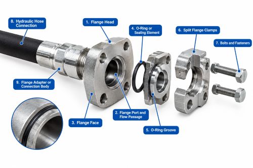
Although designs can vary depending on the manufacturer and application, most hydraulic hose flange assemblies contain several important components.
1. Flange Head
The flange head is the main structural part of the assembly. It provides the mounting surface that connects the hydraulic hose assembly to the corresponding port or equipment.
Because the flange is exposed to hydraulic pressure and mechanical loads, it needs to have sufficient strength and dimensional accuracy. Its size, shape, and bolt-hole configuration must match the mating connection.
A properly manufactured flange head also helps maintain alignment between the hose and the hydraulic equipment.
2. Flange Port and Flow Passage
Inside the flange is the flow passage through which hydraulic fluid travels.
The size and shape of this passage can affect fluid flow, pressure loss, and overall system efficiency. A passage that is too small may restrict flow, while an improperly machined passage can create unwanted turbulence or pressure loss.
For this reason, the internal passage should be designed to match the hydraulic hose and the requirements of the system.
3. Flange Face
The flange face is the surface that meets the mating port or connection.
In many hydraulic flange designs, the sealing element sits between the flange face and the mating surface. The two surfaces must be properly aligned and free from significant damage or contamination.
Scratches, dents, dirt, or other imperfections on the sealing area can interfere with proper sealing and may eventually result in hydraulic leaks.
4. O-Ring or Sealing Element
The O-ring is one of the most important parts of an O-ring face-seal flange connection.
Its main job is to prevent hydraulic fluid from escaping through the joint. When the flange is tightened against the mating surface, the O-ring is compressed within its groove to create a reliable seal.
O-rings are available in different materials, and the correct material depends on factors such as hydraulic fluid, operating temperature, pressure, and environmental conditions.
An O-ring that is damaged, incorrectly sized, or incompatible with the hydraulic fluid may fail prematurely.
5. O-Ring Groove
The O-ring groove is the machined recess that holds the sealing element in position.
The groove needs to have the correct dimensions and surface finish. If it is too deep, too shallow, damaged, or improperly machined, the O-ring may not seal correctly.
During installation, the O-ring should also be positioned carefully to prevent twisting, cutting, or pinching.
6. Split Flange Clamps
Many hydraulic flange assemblies use split flange clamps to secure the flange head to the mating port.
The clamps typically consist of two halves that fit around the flange and are secured with bolts. Once tightened, they hold the flange firmly against the mating surface.
Split flange designs are particularly useful because they allow the connection to be assembled and removed without requiring the entire hose assembly to be rotated.
The clamps must be correctly sized for the flange being used. Mixing incompatible flange and clamp sizes can compromise the connection.
7. Bolts and Fasteners
Bolts are responsible for applying the clamping force that holds the flange assembly together.
Correct bolt selection and tightening are important for maintaining a reliable connection. The bolts need to provide enough force to maintain sealing under pressure without causing unnecessary stress or damage to the flange or sealing element.
Both under-tightening and over-tightening can cause problems. Loose bolts may allow movement or leakage, while excessive torque can damage components or distort the connection.
Whenever possible, follow the manufacturer’s recommended tightening sequence and torque specifications.
8. Hydraulic Hose Connection
The hose connection is the part of the assembly that joins the flange to the hydraulic hose.
The flange and hose must be properly matched in terms of size, pressure rating, and application requirements. The hose end is normally attached using an appropriate crimped connection or other approved assembly method.
Correct hose assembly is just as important as the flange itself. Even a high-quality flange can perform poorly if the hose is incorrectly installed or damaged.
9. Flange Adapter or Connection Body
Some hydraulic hose flange assemblies incorporate an adapter or connection body between the flange and another type of connection.
Adapters can provide flexibility when connecting components with different port configurations, thread types, or orientations.
For example, an adapter may be used when a hydraulic hose needs to connect to equipment with a particular threaded or flanged port. The adapter must still be selected according to the required pressure, size, sealing method, and connection standard.
How Do Hydraulic Hose Flange Components Work Together?
A hydraulic hose flange is more than just a piece of metal attached to a hose. Its components work together to create a pressure-resistant and leak-resistant connection.
The hydraulic hose carries fluid toward the flange assembly. The flange provides the structural connection, while the O-ring or other sealing element prevents fluid from escaping at the joint.
The clamps and bolts then provide the necessary clamping force to keep the flange firmly against the mating surface.
When everything is correctly matched and installed, the assembly can withstand hydraulic pressure, vibration, and normal mechanical loads.
This is why replacing or selecting individual flange components without considering the complete assembly can sometimes lead to connection problems.
Common Materials Used for Hydraulic Hose Flanges
Hydraulic hose flanges are commonly manufactured from materials selected for strength, durability, corrosion resistance, and compatibility with the operating environment.
Carbon Steel
Carbon steel is widely used because it provides good mechanical strength and is suitable for many industrial hydraulic applications.
Surface treatments such as zinc plating can improve corrosion resistance and extend service life.
Stainless Steel
Stainless steel is commonly selected when corrosion resistance is especially important. It can be useful in harsh environments where moisture, chemicals, or corrosive conditions may affect standard carbon steel components.
The additional corrosion resistance can make stainless steel a practical choice for demanding applications, although material selection should always consider the specific operating conditions.
SAE Code 61 vs. Code 62 Hydraulic Flanges
SAE Code 61 and Code 62 are two common hydraulic flange configurations.
Code 61 flanges are widely used in hydraulic systems and are available in a range of sizes and pressure ratings. Code 62 designs are generally associated with heavier-duty applications and higher pressure requirements.
The two types can look similar, but their dimensions, bolt patterns, and pressure capabilities can differ.
They should not be treated as interchangeable simply because they have a similar appearance. Always check the applicable standard, dimensions, pressure rating, and equipment specifications before selecting a replacement.
What to Consider When Choosing a Hydraulic Hose Flange
Choosing the right hydraulic hose flange involves more than simply matching the hose diameter.
Consider the following factors:
Hose Size
The flange must be compatible with the hydraulic hose size and flow requirements.
Pressure Rating
Always select a flange assembly that is rated for the maximum working pressure of the hydraulic system. Pressure spikes should also be considered where applicable.
Material
Choose the flange material based on strength, corrosion resistance, temperature, and environmental conditions.
Sealing Element
The O-ring or other seal should be compatible with the hydraulic fluid and operating temperature.
Connection Standard
Confirm whether the system requires SAE Code 61, Code 62, or another flange configuration.
Operating Temperature
Temperature can affect both the flange material and sealing element. Make sure all components are suitable for the expected temperature range.
Application
Consider vibration, mechanical loading, installation space, maintenance requirements, and the overall working environment.
Common Problems With Hydraulic Hose Flange Components
Even a properly designed flange can develop problems if it is incorrectly installed, damaged, or used outside its intended operating conditions.
Hydraulic Leaks
Leaks can result from damaged O-rings, incorrect seals, loose fasteners, damaged flange faces, or improper installation.
Flange Misalignment
If the flange is forced into position or the hose is under excessive mechanical stress, the connection may become misaligned. This can place unnecessary loads on the flange and hose.
Damaged Sealing Surfaces
Dents, scratches, corrosion, or contamination on the flange face can prevent the sealing element from working properly.
Incorrect Bolt Torque
Incorrect tightening can also create problems. Too little torque may allow leakage or movement, while excessive torque may damage the connection.
Hose Damage
Excessive bending, twisting, abrasion, vibration, and pressure spikes can damage the hose connected to the flange. The hose and flange should therefore be treated as one complete assembly when inspecting the system.
How to Install a Hydraulic Hose Flange Correctly
Proper installation is essential for reliable performance.
Before installation, inspect the flange, hose, O-ring, clamps, and fasteners for damage. Clean the mating surfaces and make sure there is no dirt, metal debris, or other contamination.
Position the O-ring correctly in its groove and carefully align the flange with the mating port. Avoid forcing the components into position.
Install the flange clamps and bolts, then tighten the bolts evenly according to the manufacturer’s recommended sequence and torque.
The hose should also be routed without excessive bending, twisting, or mechanical tension.
After installation, pressurize the system carefully and inspect the connection for signs of leakage or movement before putting the equipment into full operation.
Hydraulic Hose Flange Maintenance Tips
Regular inspection can help identify problems before they cause equipment downtime.
During maintenance, check for:
1. Hydraulic fluid leakage around the flange
2. Damaged or missing O-rings
3. Loose fasteners
4. Corrosion on the flange or clamps
5. Scratches or damage to sealing surfaces
6. Hose abrasion or cracking
7. Excessive hose bending or twisting
8. Signs of flange movement or misalignment
9. If an O-ring or other sealing component shows signs of damage, replacing it early is usually preferable to waiting until a leak develops.
For critical hydraulic equipment, inspection intervals should follow the equipment manufacturer’s recommendations and the actual operating conditions.
Frequently Asked Questions
What are the main components of a hydraulic hose flange?
The main components can include the flange head, flow passage, flange face, O-ring, O-ring groove, split flange clamps, bolts, and hydraulic hose connection. Some assemblies may also include an adapter or additional sealing components.
What does the O-ring do in a hydraulic hose flange?
The O-ring provides the primary seal between the flange and mating surface in compatible flange designs. It prevents hydraulic fluid from escaping through the connection.
What is the difference between SAE Code 61 and Code 62 flanges?
Code 61 and Code 62 are different SAE flange configurations with differences in dimensions, bolt arrangements, and pressure capabilities. Code 62 is generally used for heavier-duty applications. The correct choice depends on the equipment and system requirements.
Can hydraulic hose flanges handle high pressure?
Yes. Properly specified hydraulic hose flange assemblies can be used in high-pressure hydraulic systems. However, every component, including the flange, hose, clamps, bolts, and sealing elements, must be rated for the application.
How do I choose the correct hydraulic hose flange?
Start by checking the hose size, flange standard, pressure rating, material, sealing element, hydraulic fluid, operating temperature, and equipment connection. These factors should all be compatible with one another.
How often should hydraulic hose flanges be inspected?
Inspection frequency depends on the equipment, operating pressure, vibration, environment, and manufacturer’s recommendations. Systems operating under severe conditions may require more frequent inspections.
Conclusion
A hydraulic hose flange is a carefully designed connection made up of several components that work together to handle hydraulic pressure and prevent leakage. The flange body provides structural support, the flow passage carries hydraulic fluid, the O-ring provides sealing, and the clamps and bolts hold the assembly securely in place.
Choosing the correct flange requires attention to more than size alone. Pressure rating, material, sealing method, flange standard, hose compatibility, temperature, and application conditions all matter.
With the right components and proper installation, hydraulic hose flanges can provide strong and dependable connections for a wide range of industrial and mobile hydraulic systems.
Post time: Oct-07-2026