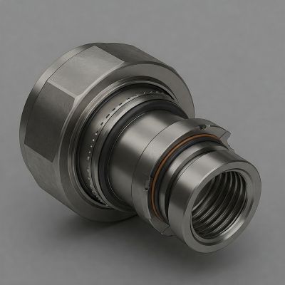
SAE O-Ring ports are a cornerstone of leak-free, high-pressure fluid connections in hydraulic and pneumatic systems. Designed with a machined groove for an elastomeric O-ring, these ports ensure a reliable seal even under extreme operating conditions.
In hydraulic and pneumatic applications, ensuring system integrity and preventing leaks is crucial. O-Ring ports offer an effective and efficient solution by creating a tight seal between the port and the fitting.
In this guide, you’ll learn everything you need to know about SAE O-Ring port dimensions, including standards, sizing charts, installation best practices, and troubleshooting tips.
What Is an SAE O-Ring Port?
SAE O-Ring ports are standardized fluid connection points specified under SAE J514 and ISO 11926. These ports use an elastomeric O-ring compressed into a precision-machined groove to create a pressure-tight seal.
SAE J514 / ISO 11926 Standards
SAE J514 is a U.S.-based standard governing the design and dimensions of hydraulic ports and fittings. While ISO 11926 is an international equivalent, often used in global manufacturing.
Common Applications
➡️ Industrial hydraulics
➡️ Mobile equipment
➡️ Aerospace systems
➡️ Marine and offshore rigs
Why O-Ring Ports Are Used
Benefits Over Other Port Types
➡️ More compact than flare or pipe threads
➡️ Better sealing performance in dynamic environments
Leak Prevention & High-Pressure Performance
➡️ O-Rings maintain a tight seal even with vibration and pressure fluctuations
➡️ Ideal for systems with pressures exceeding 3000 PSI
Ease of Installation and Maintenance
➡️ Requires minimal torque
➡️ Quick and reliable assembly without special tools
SAE O-Ring Port Components
Here are the components of SAE O-Ring port that make up the fitting:
1. Port: Precision-machined cavity in the housing
2. O-Ring: An Elastomer ring that seals the interface
3. Retaining Ring: Holds the O-ring in place during assembly (optional, based on design)
4. Thread and Counterbore: Threads for fitting engagement; counterbore aligns the O-ring
Understanding SAE O-Ring Port Dimensions
Key Dimensional Terms
➡️ Thread Size: Unified inch threads (e.g., 7/16-20 UNF)
➡️ O-Ring Groove Diameter: Diameter of the groove holding the O-ring
➡️ Counterbore Depth & Diameter: Controls how far the fitting sits into the port
➡️ Spotface Diameter: Provides a flat surface for the fitting to contact
Tolerances and Manufacturing Considerations
➡️ Precision machining is essential
➡️ Deviations can lead to leaks or poor-fitting engagement
SAE O-Ring Port Dimensions Chart
|
Dash Size |
Thread Size |
Counterbore Dia (in) |
Spotface Dia (in) |
Min Depth (in) |
O-Ring Size |
|
-4 |
7/16-20 |
0.391 |
0.50 |
0.30 |
004 |
|
-6 |
9/16-18 |
0.516 |
0.625 |
0.34 |
006 |
|
-8 |
3/4-16 |
0.641 |
0.75 |
0.38 |
008 |
|
-10 |
7/8-14 |
0.766 |
0.875 |
0.41 |
010 |
|
-12 |
1 1/16-12 |
0.891 |
1.00 |
0.44 |
012 |
How to Measure and Identify SAE O-Ring Ports
Step-by-Step Guide
1. Clean the port and inspect for debris or damage
2. Measure the thread diameter with a caliper
3. Use a thread pitch gauge to determine the thread count
4. Check the counterbore and spotface diameters
Recommended Tools
➡️ Digital caliper
➡️ Thread pitch gauge
➡️ O-Ring size chart
Common Mistakes
➡️ Confusing SAE threads with NPT
➡️ Measuring damaged or worn ports
Installation Tips for SAE O-Ring Fittings
Proper Fitting Alignment
➡️ Align fitting perpendicular to port
➡️ Avoid cross-threading
Torque Specifications
➡️ Follow manufacturer guidelines
➡️ Do not overtighten—this can crush the O-ring
Avoiding Seal Damage
➡️ Lubricate O-Ring before installation
➡️ Inspect O-Rings for wear or defects before use
Troubleshooting Common Issues
Leaks at the Port Face
➡️ Check for damaged or misaligned O-rings
➡️ Verify fitting torque
O-Ring Wear or Extrusion
➡️ Caused by high pressure, poor alignment, or chemical degradation
Thread Damage and Cross-Threading
➡️ Avoid forcing fittings
➡️ Use appropriate tools and alignment techniques
Industry Standards and Compatibility
Related Standards
➡️ SAE J1926 (port dimensions)
➡️ ISO 11926
➡️ DIN 3852
Interchangeability
➡️ Some overlap exists between SAE and ISO ports
➡️ Always verify compatibility before assembly
Material Considerations
➡️ Steel, stainless steel, brass options
➡️ O-Rings available in Buna-N, Viton, EPDM, etc.
Frequently Asked Questions (FAQs)
Can SAE O-Ring ports be reused?
Yes, but always inspect the O-ring and port for wear.
What materials are O-Rings typically made from?
Common materials include Nitrile (Buna-N), Viton, and EPDM.
Are SAE O-Ring ports suitable for high-vibration environments?
Yes, when installed correctly with quality components.
Conclusion
Understanding SAE O-Ring port dimensions is essential for building safe, leak-free, and high-performing hydraulic and pneumatic systems. Always refer to standard sizing charts, use proper tools, and follow installation best practices to ensure long-term reliability.
Explore our full range of SAE fittings, adapters, and O-Ring kits. Need help with sizing or custom solutions? Contact us at nancy@sannke.com or leave us a message.
Post time: May-05-2025


