
Hydraulic compression fittings are essential components in fluid power systems, providing secure, leak-tight connections in high-pressure and demanding environments. Used across mobile and industrial applications, they help ensure system safety, reliability, and performance.
In hydraulic systems, accurate diagrams and precise dimensional standards are critical, minor dimensional errors can lead to leaks, wear, or system failure.
This guide is intended for engineers, maintenance teams, OEMs, procurement professionals, and system designers seeking a clear, professional understanding of hydraulic compression fitting diagrams and dimensional standards.
What Are Hydraulic Compression Fittings?
Hydraulic compression fittings are mechanical connectors designed to join tubing to hydraulic components by compressing a ferrule (or ferrules) onto the tube as the nut is tightened. This compression creates a strong mechanical grip and a metal-to-metal seal capable of withstanding high pressures.
When the nut is tightened onto the fitting body, the ferrule(s) are driven into the tube’s outer surface. This action “bites” into the tube, forming a secure seal and preventing both leakage and tube pull-out.
Key Components
1. Body
The body houses the internal seat and provides the threaded connection point to ports, valves, or other fittings.
2. Ferrule(s)
➡️ Single ferrule: Combines sealing and gripping in one component.
➡️ Double ferrule: Uses a front ferrule for sealing and a back ferrule for gripping and vibration resistance.
3. Nut
During tightening, the nut exerts axial force on the ferrule or ferrules, allowing for appropriate compression and sealing.
Compression vs Flare and Threaded Fittings
Unlike flare fittings, which rely on a flared tube end, or threaded fittings that seal via threads or O-rings, compression fittings seal by mechanical deformation of the ferrule. This makes them particularly suitable for high-pressure, vibration-prone hydraulic systems.
Why Diagrams and Dimensional Accuracy Matter
1. Impact on Sealing Performance
Incorrect dimensions, such as mismatched tube OD or ferrule geometry, can prevent proper ferrule bite, leading to leaks or tube slippage under pressure.
2. Safety in High-Pressure Systems
Hydraulic systems operate at pressures that can exceed thousands of PSI. Dimensional inaccuracies can result in sudden failures, posing serious safety risks to personnel and equipment.
3. System Efficiency and Component Lifespan
Leaks and misalignments reduce system efficiency, increase energy consumption, and accelerate wear on pumps, valves, and seals.
4. Compliance with Industry Standards
Adhering to recognized dimensional standards ensures compliance with regulatory and industry requirements, particularly in safety-critical applications.
Anatomy of a Hydraulic Compression Fitting
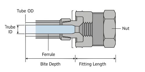
A labeled diagram is one of the most valuable tools for understanding compression fittings. It clearly identifies each component and the critical dimensions that govern performance.
1. Tube Outside Diameter (OD): The primary sizing reference for compression fittings
2. Tube Inner Diameter (ID): Affects pressure rating and flow capacity
3. Ferrule Angle and Bite Depth: Determines sealing effectiveness and pull-out resistance
4. Thread Size and Pitch: Ensures compatibility with ports and mating components
5. Body Hex Dimensions: Important for tool access and installation
6. Overall Fitting Length: Affects system layout and clearance
Tolerance and Machining Precision
High-quality compression fittings are manufactured to tight tolerances. Even small variations can compromise sealing, particularly in high-pressure or cyclic-load environments.
Common Hydraulic Compression Fitting Types
➡️ Straight Compression Fittings: Used for inline connections
➡️ Elbow Compression Fittings (45° and 90°): Allow directional changes in tubing runs
➡️ Tee Compression Fittings: Enable branching connections
➡️ Bulkhead Compression Fittings: Provide secure pass-through connections across panels
➡️ Male vs Female Threaded Connections: Selected based on port design and system layout
Hydraulic Compression Fitting Dimensional Standards
International Standards Overview
1. ISO Standards (e.g., ISO 8434): Widely used in global hydraulic systems
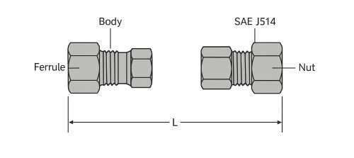
2. SAE Standards (e.g., SAE J514): Common in North American applications
3. DIN Standards (e.g., DIN 2353): Prevalent in European hydraulic systems
Metric vs Imperial Systems
Hydraulic fittings are produced in both metric and inch-based dimensions. Mixing systems can lead to improper sealing and mechanical failure.
Interchangeability Limitations
Fittings that appear similar may not be interchangeable due to differences in thread forms, sealing angles, or tolerances. Always verify standard compatibility.
Reading and Interpreting Hydraulic Fitting Diagrams
Professional diagrams convey critical information beyond basic dimensions.
1. Understanding technical symbols and line conventions
2. Reading dimension callouts and tolerance ranges
3. Identifying surface finish and material specifications
4. Recognizing thread types and sealing methods from drawings
5. Accurate interpretation of diagrams ensures correct selection, installation, and inspection.
Material and Pressure Rating Considerations
Common Materials
➡️ Carbon Steel: High strength and cost-effective for most hydraulic systems
➡️ Stainless Steel: Superior corrosion resistance for harsh environments
➡️ Brass: Limited hydraulic use due to lower pressure ratings
Pressure and Temperature Ratings
Pressure ratings depend on fitting size, material, and applicable standard. Temperature extremes and fluid compatibility must also be considered during selection.
Installation Guidelines Based on Diagrams and Dimensions
Proper installation begins with the correct interpretation of diagrams.
1. Tube cutting, deburring, and cleaning requirements
2. Correct assembly sequence using dimensional references
3. Torque specifications or turns-from-finger-tight methods
4. Avoiding common mistakes caused by misreading dimensions
Inspection and Quality Control
Before system startup:
➡️ Verify tube and fitting dimensions
➡️ Measure tube OD and inspect ferrule placement
➡️ Use diagrams for visual comparison
➡️ Perform leak testing and pressure validation
Quality control reduces downtime and prevents costly failures.
Common Dimensional Issues and Troubleshooting
1. Mismatched tube OD and fitting size
2. Incorrect ferrule orientation or positioning
3. Thread incompatibility from mixed standards
4. Tube or fitting deformation due to over-tightening
5. Early identification of these issues minimizes rework and system risk.
Application-Specific Considerations
1. Mobile Hydraulics: Resistance to vibration and shock loads
2. Industrial Systems: Long-term reliability and standardization
3. High-Vibration Environments: Preference for double ferrule designs
4. Safety-Critical Systems: Strict adherence to standards and documentation
Selecting the Right Hydraulic Compression Fitting
1. Match dimensions precisely to system requirements
2. Confirm compliance with applicable standards
3. Ensure compatibility with existing components
4. Review supplier datasheets and technical drawings
5. Proper selection reduces installation errors and improves system reliability.
Best Practices for Professionals
1. Maintain dimensional consistency across systems
2. Always reference manufacturer diagrams and specifications
3. Keep detailed documentation for maintenance and audits
4. Train technicians on dimensional standards and interpretation
Frequently Asked Questions
Are hydraulic compression fittings interchangeable across standards?
Generally no. Differences in threads, sealing angles, and tolerances can prevent proper sealing.
How critical are tolerances in high-pressure systems?
Extremely critical. Small deviations can cause leaks or mechanical failure.
Can compression fittings be reused?
Reusability depends on the fitting design and condition. Many manufacturers recommend limited or no reuse.
What diagrams should always be referenced before installation?
Manufacturer assembly diagrams, dimensional drawings, and applicable standard references should always be consulted.
Conclusion
Accurate diagrams and dimensional standards are the foundation of safe, efficient, and reliable hydraulic systems. For professionals working in high-pressure environments, precision is not optional, it is a requirement.
By understanding compression fitting geometry, adhering to recognized standards, and using detailed diagrams throughout design, installation, and maintenance, organizations can reduce failures, improve safety, and extend equipment life.
Post time: Dec-15-2025